Low Voltage High Current DC Power Supply 1000A 1500A 2000A 3000A 4000A 5000A Up to 10kA

Low Voltage High Current DC Power Supply 1000A 1500A 2000A 3000A 4000A 5000A Up to 10kA

  • Low voltage and high current output
  • Rated voltage 5V 10V 15V 30V
  • Rated current 1000A 1500A 2000A 3000A 4000A 5000A up to 10kA
  • Comprehensive customized solutions case by case
  • 4 digits LED display for voltage and current
  • Low ripple, high stability
  • List mode function, Auto Run function, Remote sensing function
  • No overshoot during startup
  • Adjustable voltage rise time
  • Remote ON/OFF control
  • Preset function, setting of voltage and current with output open circuit
  • Multiple protections: OVP, OTP, ACF and current limit protections
  • Standard interface: RS232 & RS485, support ModBus-RTU commands
  • Optional interface: DC 0-5V, 0-10V or 4-20mA analog interface for control and feedback
Quote Now

    Quick Help: Contact one of our experts and we'll get back to you in 24 hours!

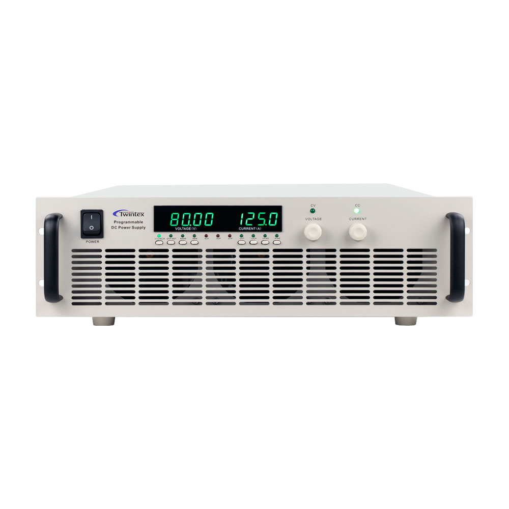
    As the name implies, low voltage high current DC power supplies delivers high current output at low voltage to a load. In general, low voltage high current DC power supplies are designed for industrial testing and power electronics development. Output voltage is normally below 60V, typically 5V 10V 15V, and output current is always 500 amps or higher.

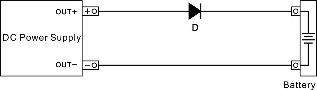
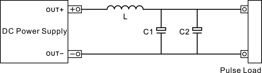
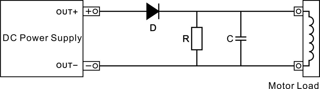
    As the electronic industry grows, so dose demands for high power density, high current capacity, precise control and output. Low voltage high current DC power supplies are essential in a wide range of applications in modern industry, such as battery charging, motor testing, electric vehicles components and systems testing, powering electrolysis systems, etc.

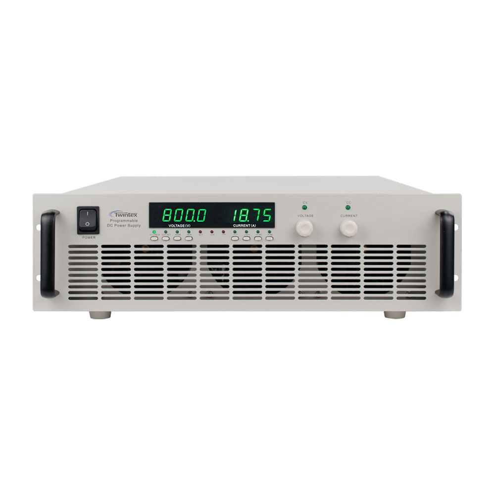
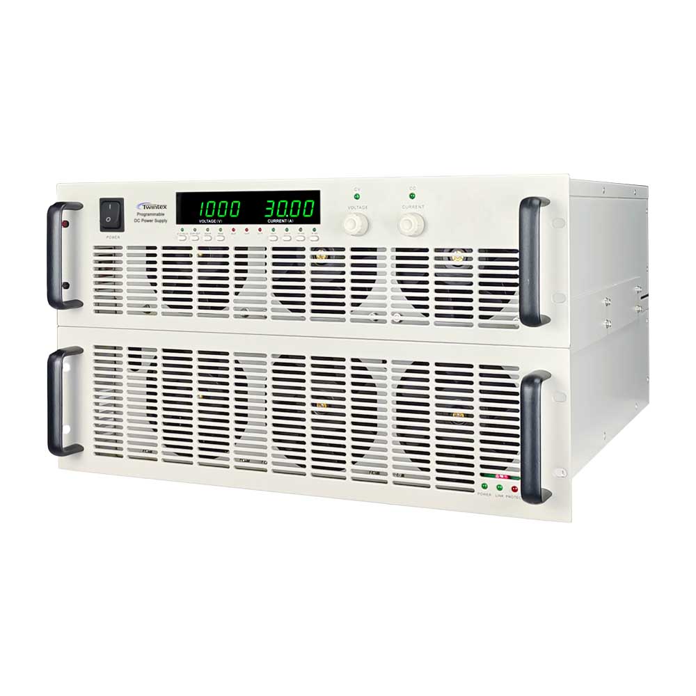
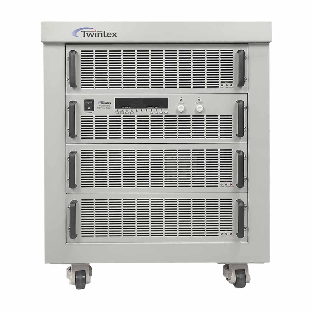
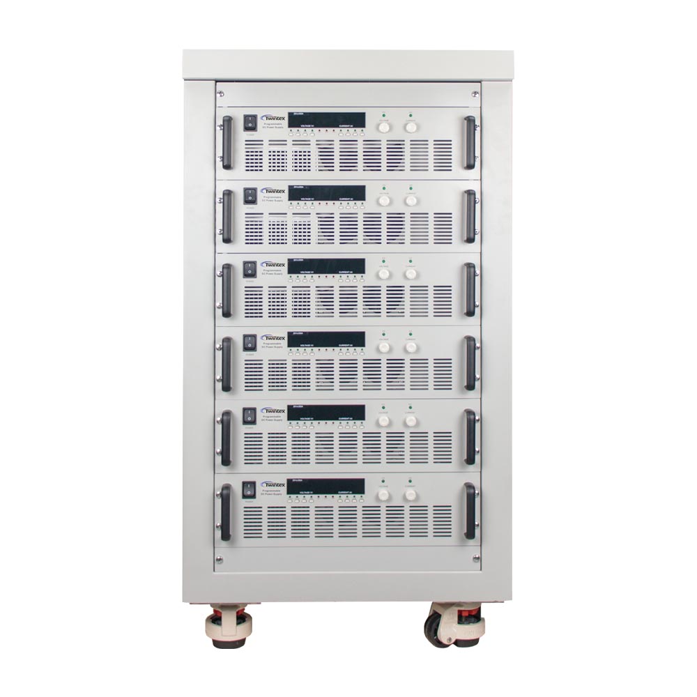
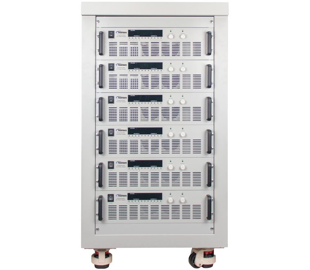
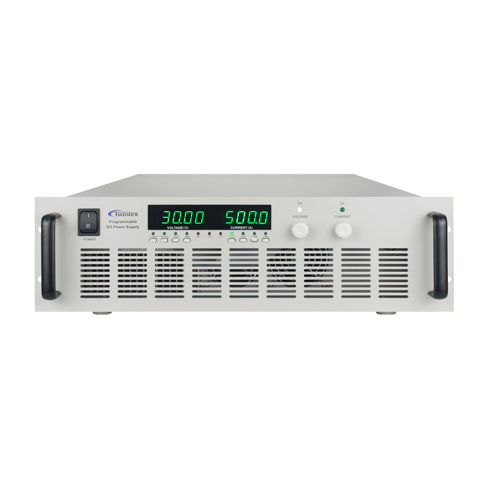
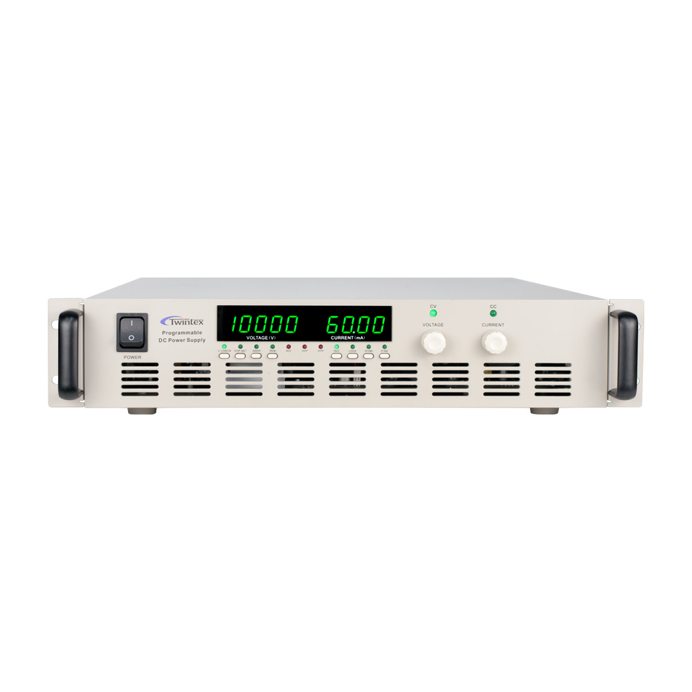
    TWINTEX PCL series low voltage high current switch mode DC power supplies adopts PWM technology, which greatly reduces switching consumption and therefore facilitates switching function with high efficiency and high stability. These high current DC power supplies provide high current output with good stability for applications listed below.

    Application Description
    Battery charging High current power facilitates rapid charging of electric vehicle batteries and other high-power battery packs.
    DC motors High current power drives DC motors and facilitates verifying its performance and identifying potential issues
    Semiconductor testing Provides power supply for system-level testing and component burn-in testing.
    Spot welding High current power to welding machines that join metal surface points by the heat obtained from resistance to electric current.
    Electrolysis High current power to an electrolyte which is producing chemical reactions at the electrodes and decomposition of the materials.
    Transformer testing High current power to warm up transformer coils, especially before a cold start.
    Superconducting cable testing High current power is crucial to assess the superconducting cable’s ability to handle significant power transmission.
    Power relay testing High current power is essential in verifying the relay’s functionality and safety under high current conditions.

    Product Parameters

    Model Rated Output Cabinet size   Model Rated Output Cabinet size
    V A W   V A W
    PCL10-1000 0~10V 0~1000A 10kW 3U
    PCL10-2000 0~20V 0~2000A 20kW 6U
    PCL10-3000 0~10V 0~3000A 30kW 12U PCL40-500 0~40V 0~500A 20kW 6U
    PCL10-4000 0~10V 0~4000A 40kW 12U PCL40-750 0~40V 0~750A 30kW 6U
    PCL10-5000 0~10V 0~5000A 50kW 20U PCL40-1500 0~40V 0~1500A 60kW 12U
    PCL10-4000 0~10V 0~10000A 100kW 40U PCL40-3000 0~40V 0~3000A 120kW 30U
    PCL15-750 0~15V 0~750A 11.25kW 3U PCL50-300 0~50V 0~300A 15kW 3U
    PCL15-1500 0~15V 0~1500A 22.5kW 6U PCL50-600 0~50V 0~1600A 30kW 6U
    PCL15-2000 0~15V 0~2000A 30kW 12U PCL50-1500 0~50V 0~1500A 45kW 12U
    PCL15-3000 0~15V 0~3000A 45kW 12U PCL50-2100 0~50V 0~2100A 105kW 30U
    PCL15-4500 0~15V 0~4000A 60kW 20U PCL50-3000 0~50V 0~3000A 150kW 30U
    PCL20-600 0~20V 0~600A 12kW 3U PCL60-250 0~60V 0~250A 15kW 3U
    PCL20-1200 0~20V 0~1200A 24kW 6U PCL60-500 0~60V 0~500A 30kW 6U
    PCL20-3000 0~20V 0~3000A 60kW 20U PCL60-1000 0~60V 0~1000A 60kW 12U
    PCL20-5000 0~20V 0~5000A 100kW 30U PCL60-1500 0~60V 0~1500A 90kW 20U
    PCL30-500 0~30V 0~500A 15kW 3U PCL60-2000 0~60V 0~2000A 120kW 30U
    PCL30-1000 0~30V 0~1000A 30kW 6U PCL100-150 0~100V 0~150A 15kW 3U
    PCL30-1500 0~30V 0~1500A 45kW 12U PCL100-300 0~100V 0~300A 30kW 6U
    PCL30-2000 0~30V 0~2000A 60kW 12U PCL100-600 0~100V 0~600A 60kW 12U
    PCL30-3000 0~30V 0~3000A 90kW 20U PCL100-900 0~100V 0~900A 90kW 20U
    PCL30-4000 0~30V 0~4000A 120kW 30U PCL100-1500 0~100V 0~1500A 150kW 30U
    PCL30-5000 0~30V 0~5000A 150kW 40U PCL100-1950 0~100V 0~1950A 195kW 40U
    Application Description
    Battery charging High current power facilitates rapid charging of electric vehicle batteries and other high-power battery packs.
    DC motors High current power drives DC motors and facilitates verifying its performance and identifying potential issues
    Semiconductor testing Provides power supply for system-level testing and component burn-in testing.
    Spot welding High current power to welding machines that join metal surface points by the heat obtained from resistance to electric current.
    Electrolysis High current power to an electrolyte which is producing chemical reactions at the electrodes and decomposition of the materials.
    Transformer testing High current power to warm up transformer coils, especially before a cold start.
    Superconducting cable testing High current power is crucial to assess the superconducting cable’s ability to handle significant power transmission.
    Power relay testing High current power is essential in verifying the relay’s functionality and safety under high current conditions.

    For the purpose of product improvement, specifications are subject to change without prior notice.

    Why Choose Us.

    • With years of industry knowledge, we bring unparalleled expertise to every project.
    • Our rigorous standards ensure top-notch quality in all our products.
    • Constantly striving for new and improved solutions, we never stop innovating.
    • Tailoring our services to your unique needs, we ensure complete satisfaction.
    • Experience excellence with our dedicated support and customer-focused approach.

    Frequently Asked Questions

    A DC power supply is to supply voltage and current in constant voltage (CV) or constant current (CC) mode within the rated output range. Such working characteristics is called a constant voltage/constant current automatic cross-over type. This permits continuous transition from constant current to constant voltage modes in response to the load change. The intersection of constant voltage and constant current modes is called the crossover point. Below figure shows the relationship between this crossover point and the load.

    In CV mode, a regulated output voltage is provided. The output voltage remains constant as the load increases while the output current changes in response to the load changes, up till the present current limit point is reached. At that point, the output current becomes constant and the output voltage drops in proportion to the further increases in load.

    Similarly, in CC mode, crossover from the CC to CV mode automatically occurs from a decrease in the load. A regulated output current is provided. The output current remains constant as the load decreases while the output voltage changes in response to the load changes.

    A power supply with CV and CC operation mode can be operated in only one mode according to load situation. The power supply is in CV mode when the actual load is over the preset load capacity; and the power supply is in CC mode when the actual load is below the preset load capacity.

    When the power supply is connected to a big capacitive load, it always causes increase to the output voltage in a power supply. The output voltage may make fast increase to the Over Voltage Protection point. It may also cause slow decrease when the output voltage is turned down.

    To solve this problem, connect a power resistor in parallel to the output terminals of the power supply; at the same time, connect a diode in serial between output terminals and the load.

    When an inductive load is connected to the power supply, it will cause a reverse polarity induction electric motive force when the power supply is turned on or off, or when preset the output voltage. The pulse noise caused by an inductive load will also affect the power supply, especially when the pulse noise has the same polarity with the output of power supply.

    To avoid effect or damage to the power supply, connect a diode in serial between the output terminals of power supply and the load; at the same time, connect a power resistor and a capacitor in parallel to the load to make a R-C snubbed circuit, which will significantly restraint generation of the noise.

    When use the power supply to charge a battery, such as accumulator and ni-mh battery, the recommended protection measures is to connect a diode between the power supply and the battery. When the output electrolytic capacitor of the power supply is charged, connecting a load (battery) may cause sparks. This is normal. After the two of them get to equal voltage, the sparks will disappear.

    Even if the peak current of a pulse load, such as motor, bulb, DC-DC or DC-AC converter module, does not exceed the rated current of the power supply, it will also cause voltage drop or instability to the output.

    A basic solution is to connect a inductor in serial between the power supply and the load. Or, choose a power supply with higher rated current.

    If the pulse circuit has a small pulse width or low peak current, another solution is to connect a capacitor with large capacity. A reference to choose capacity of a capacity is: 1000uF capacity to a 1A current.

    When the power supply is connected to a load that will cause reverse polarity current to the power supply output, the output voltage will increase, because the power supply cannot absorb the reverse polarity current from the load.

    A solution is to connect a diode in serial between the output terminal and the load; at the same time, connect a discharge resistor in parallel to the load to absorb the reverse polarity current. When the reverse polarity current is a peak surge, connect the large electrolytic capacitor in parallel to the two ends of the load.

    Get Quote Now!

    Welcome to discuss your purchasing requirements with our customer service.

      Get The
      Catalogue
      Document

      From more than 10 years experiences in OEM & ODM services, our sales team and technical team are always available to check and discuss your requirement details.Whether you’re looking for reliable DC motors to enhance precision in your devices or powerful AC motors for robust industrial applications, we have you covered.